FF-SIGNAL CARRIES NETWORK SIGNALS EFFECTIVELY THROUGH STRUCTURES
The FF-SIGNAL signal amplifier is an innovative passive element that relays signals and insulates the structure against cold and moisture. A mobile phone signal passing through wall structures is 30–100 times stronger when relayed through the amplifier, which enables fast and reliable connections indoors even in challenging settings.
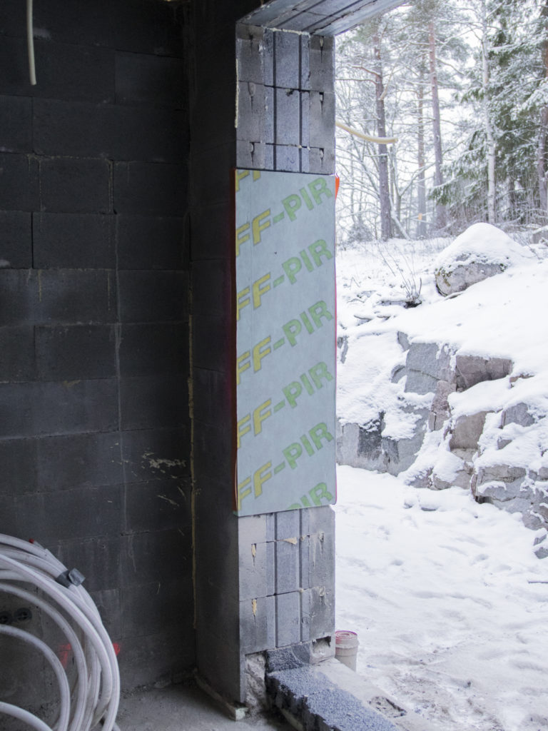
The signal amplifier is installed inside the structure, e.g., in between window frames or under thin-coat render on a concrete wall. The product is developed and manufactured in Finland, in cooperation between Finnfoam Oy and StealthCase Oy.

STARTING POINT FOR PRODUCT DEVELOPMENT
Modern construction solutions pose challenges for mobile networks. In a brand new modern block of flats, for example, the energy efficiency of windows can be so good that the balcony might be the only place where you can reliably use wireless devices. Problems also arise in old buildings that have been renovated and fitted with new windows.
Concrete structures, windows with selective coating, and other construction products that contain metal are especially disruptive for signals. As energy efficiency requirements become more stringent, the design of buildings should ensure adequate indoor reception for networks that are crucial for building safety. FF-SIGNAL was designed to solve reception issues in these new and challenging conditions.
OPERATION AND TECHNICAL SPECIFICATIONS
FF-SIGNAL receives the incoming signal from a base station and relays the signal through the wall along its entire length and thus maintains the strength of the outdoor signal inside the apartment. The FF-SIGNAL amplifier works both ways, also from indoors to outdoors. The signal relaying capacity of the FF-SIGNAL element has been measured and tested in laboratory conditions and confirmed in various field tests.
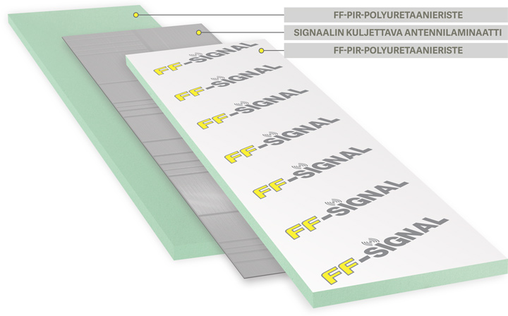
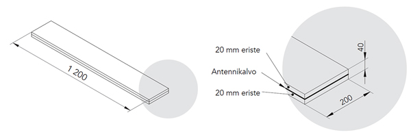
FF-SIGNAL consists of two FF-PIR (polyisocyanurate) insulator sheets (20 mm) manufactured by Finnfoam Oy and a signal amplifier or antenna element that is placed in between them.
FF-SIGNAL
- Maintenance-free
- No thermal bridging
- Rust-proof
- CE certified
- Certified M1 for best indoor air quality
- Patented solution
- Does not require electricity to function
- Works with all operators’ networks
- Supports the most common IoT technologies
- Cost-effective
- As the solution is based on a dedicated device, it does not affect the purchase of windows for the building.
DIMENSIONS OF THE FF-SIGNAL ELEMENT:
Size: 200 x 1 200 mm and 300 x 1 200 mm
STORAGE
FF-SIGNAL can withstand UV radiation during construction. For long-term storage, the products must be protected against UV radiation. On site, the FF-SIGNAL signal amplifiers must be protected from weather conditions before installation.
COST-EFFECTIVENESS
FF-SIGNAL requires no maintenance, and it will work inside the wall of a building for decades, which makes the passive FF-SIGNAL an extremely competitive solution for reception problems over its lifecycle when compared to retrofit solutions.
Recipient of the Technology to Products Foundation’s Recognition Award in 2017 – FF-SIGNAL promotes sustainable and productive built environment.
INSERTION LOSS WITH FF-SIGNAL
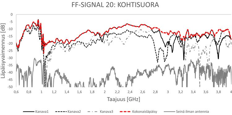
FF-SIGNAL offers extremely low insertion loss, which remains at all times below the level recommended/specified by operators (-15 dB) to ensure the operation of their networks. The insertion loss of modern structures typically falls between -30…-70 dB.
INSTALLATION
EFFECTIVE AREA, INSTALLATION LOCATIONS, AND THE NUMBER OF ANTENNAS
When deciding on where to install the elements, walls with a wide view of the horizon are recommended, where possible. You should also avoid sides of the building that are affected by tall obstructions, as that will have a negative impact on mobile phone signals on the outside to start with. If at all possible, you can improve the effectiveness of the antenna elements by installing them on at least two walls pointing in different directions, as that will ensure the best possible reception and support for different operators.
The FF-SIGNAL amplifier elements should be installed in open spaces where mobile devices are most commonly used to ensure that signals can disperse freely through the building. We do not recommend installing amplifiers at the corners of rooms. The signal is unable to penetrate concrete dividing walls effectively, which should be taken into account in the placement of elements. For design purposes, the general rule is that a single FF-SIGNAL amplifier will ensure good reception over an approximate area of 30–40 square meters.
On a worksite or at a prefabricated house / concrete element plant, FF-SIGNAL elements can, for example, be installed:
- Onto a concrete wall, under a reveal board / trim / thin-coat render.
- Between the studs of a sealed glazing wall.
- Between the studs in a wooden house insulated with aluminum-covered insulation panels.
- In between window frames.
- In between a window frame and the door to a balcony with or without auxiliary frames.
The number of FF-SIGNAL amplifiers required depends on the desired effect and the size of the building. Included below are some examples of the recommended minimum number of devices for different buildings:
- A small studio or one-bedroom apartment, which would typically include an open living room and kitchen area, can be covered with a single FF-SIGNAL amplifier installed next to a balcony door or window.
- For a floor-through-apartment, we recommend installing FF-SIGNAL elements at both ends of the apartment.
- In large modern stone apartment building, a whole floor could, for example, be covered with 3–4 elements placed on 2–3 sides of the building.
- A suitable spacing for installing the elements into a facade of an office building is 3–5 meters.
Installation Method
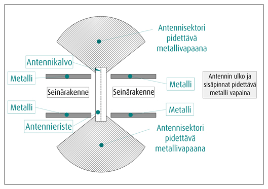
In order to ensure that the FF-SIGNAL amplifiers function as designed, the installation should be carried out with due care and in compliance with the instructions. To function without interruptions, an FF-SIGNAL element requires that both sides of the wall are free of metal objects.
Always install FF-SIGNAL elements in an upright position within the exterior envelope of the building. Do not cover the FF-SIGNAL element with metal on either side of the wall.
Always use urethane foam to seal the edges of the FF-SIGNAL element. The interior surface and joints of the wall into which the element is installed can be sealed with plastic vapor barrier tape or cloth tape. The insulation material used in the signal amplifier is, however, quite resistant against water vapor in itself. Do not cover the signal amplifier with aluminum tape or other metal items.
COVERING AN FF-SIGNAL AMPLIFIER ON AN INTERIOR WALL
FF-SIGNAL voidaan sisäseinällä päällystää millä tahansa metallittomalla levyllä. Soveltuvia rakennuslevyjä ovat esimerkiksi kipsilevy, lastulevy, OSB-levy, MDF- ja HDF-levyt. Höyrynsulkumuovin käyttö on sallittua. Seinän sisäpinta voidaan myös maalata maalilla, joka ei sisällä rauta- hiili- tai grafiittipartikkeleita. FF-SIGNAL ei saa peittää alumiinipintaisella lämmöneristeellä.
COVERING AN FF-SIGNAL AMPLIFIER ON AN EXTERIOR WALL
The external part of the FF-SIGNAL element can be covered using any non-metallic construction material that is suitable for outdoor use. Such materials include, for example, wood cladding, non-metallic facade panels, high pressure laminates, plastics-based surfaces, and stone-based facade materials (stone or concrete-based facade panels should be relatively thin, measuring 6–15 mm). Windproofing panels can also be used on top of FF-SIGNAL elements.
The exterior surface of an FF-SIGNAL element can also be covered with thin-coat render. Do not install a steel mesh over FF-SIGNAL elements and instead use nylon or fiberglass meshing for the render. Do not cover the exterior surface of an FF-SIGNAL element with aluminum-plastic composite materials.
The exterior surface of the wall can be coated with a paint that does not contain iron, carbon, or graphite particles.
Cover panels used on the outside of FF-SIGNAL elements are secured to the surrounding wall structure. Where necessary, a cover panel can also be attached directly to the signal amplifier using urethane foam, urethane foam adhesive, KiiltoFlex XPU adhesive paste, or another similar material.
CUTTING AN FF-SIGNAL AMPLIFIER TO SIZE
FF-SIGNAL amplifiers can be cut into smaller sections both vertically and horizontally as long as the element still extends throughout the entire wall structure. The FF-SIGNAL elements receive signals over their entire height, and the recommended minimum height for an element is 800 mm.
USING SCREW AND NAILS AND CUTTING FF-SIGNAL ELEMENTS
The optimal way to secure an FF-SIGNAL amplifier as part of a wall is to glue it in place using urethane foam or foam adhesive, which means that you do not have to penetrate the element using screws. You can, however, use a small number of screws through the FF-SIGNAL element where necessary to facilitate the installation.
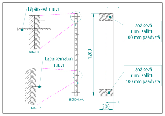
The core section of an FF-SIGNAL amplifier comprises an antenna membrane, which may be pierced with screws or nails in a controlled manner. However, any screws or nails secured through the membrane should be within 100 mm of the sides of the antenna insulation.
If the signal amplifier has not been shortened, you may also pierce the antenna membrane with a third screw through the midsection of the panel where necessary for installing a window, for example. Any screws secured through FF-SIGNAL amplifiers should primarily be fitted at the sides.
If an FF-SIGNAL element has been cut shorter than 900 mm, the antenna membrane may be pierced using a maximum of two screws, both of which are fitted on the sides of the insulation panel. Do not pierce shortened antenna insulation panels with three screws.
The maximum number of screws fitted through the antenna membrane at the core of an FF-SIGNAL amplifier is 1 screw / 50 cm spacing interval.
For easier installation, the FF-PIR insulation panel on either side of the antenna membrane can be pierced at multiple locations using, for example, various pins or screw pins as long as you ensure that they do not pierce the antenna membrane. Pins may be helpful for positioning an FF-SIGNAL element within an auxiliary frame or onto a timber stud before applying urethane foam. For example, 35 × 1.7 mm wire or dyckert nails can be used for this purpose. Nails or screws that do not pierce the antenna membrane may, for example, be used on the lower section of a window frame where the FF-SIGNAL panel can be secured with the nails before the urethane foam is applied.
Installation Examples
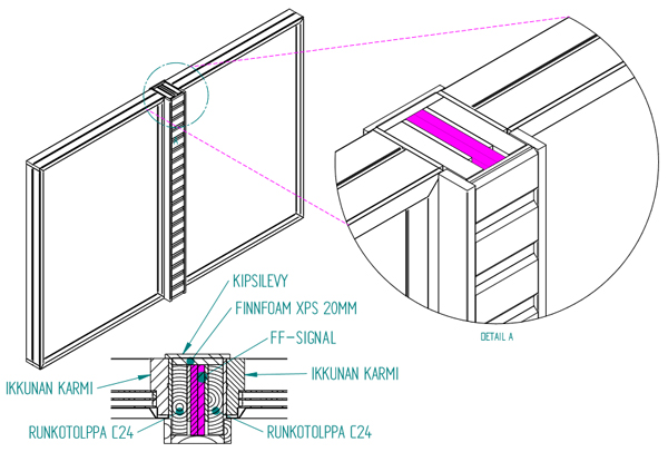
STRUCTURAL DRAWINGS
On this page you will find structural examples for FF-SIGNAL. The aim of the structural design has been to ensure that the structures are safe and efficient in terms of building physics. Particular attention has also been paid on easy and simple installation techniques, which contribute to the achievement of high-quality results.
The suitability of all structure types presented must be ensured together with a competent structural designer. Our aim is to continue adding new structural drawings for different structural solutions. All drawings can be found below in PDF and DWG formats.
FF-SIGNAL 300 mm Between a Sandwich Element and Window (PDF, 112 kB)
FF-SIGNAL_200 mm Between a Sandwich Element and Window (PDF, 113 kB)
FF-SIGNAL_Between Two Windows (PDF, 116 kB)
FF-SIGNAL Between a Window and Door (PDF, 127 kB)
Download all FF-SIGNAL drawings as a DWG file (DWG, 266 kB)